
Previously I showed how I used finite element analysis to optimize the design for the main tether. At that point I was planning to have one single tether that performed three functions: Attach the main Kevlar line to the balloon, attach the parachute cords, and hold the primary 360 camera.
Primarily to get some weight down from the top of the HAPP and lower the center of gravity (an old issue), I finally decided to split up the functions. It also allowed me to use a cheaper type of CNC milling to cut the aluminum parts. Now the balloon tether & camera mount are still combined, but the chute tether is down just above the ELS Deck.
The new, simplified balloon tether looks like this:
New design for balloon tether. Left: FEA analysis. Right: Photo with 360 camera in place after firing the cutdown pyros. Note the bit of Kevlar string remaining.
So that's the balloon tether. Now where do we put the chute tether? We want it to be lower, but we can't just bolt it onto the aeroshell or one of the core structure decks - they are too thin and would not take the shock of parachute inflation. The carbon fiber would simply shred apart, or (more likely) the various epoxy bonds or velcro straps would fail. It needs to attach to the main strut somehow.
We could cut the strut - the backbone of the core structure - and "splice in" the tether, but then we'll have to hope that whatever types of joints we create will hold up under load. A better idea is to break the chute tether into pieces. The center body inserts into the main strut and slides down to the right location. Then, the chute arms are inserted into the center body through small holes in the main strut.
It's hard to picture the design after the chute tether is installed, but perhaps you'll get an idea from these renderings:
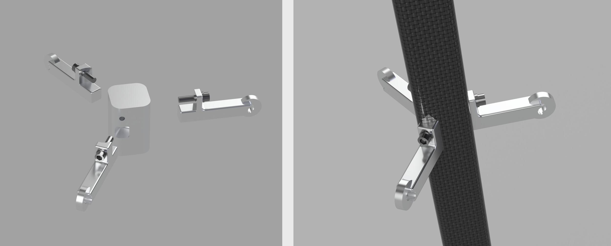
And here's the actual chute tether assembled into position:
And finally, just to prove I did my homework for optimizing strength versus weight, here's an animated FEA: